All posts by Zachary Abel

How to Make an Impenetraball!

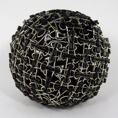
By popular demand, I am posting instructions for how to make your own Impenetraball, one of my most popular sculptures. Be warned; this is not easy, but it is certainly rewarding. And potentially lethal, in more ways than one…

Final Impenetraball

Geometry of the Impenetraball

Impenetraball schematic

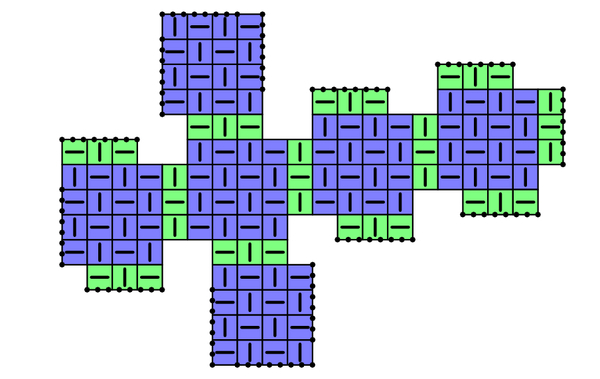
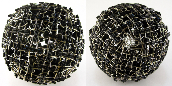
First, we must understand the geometry of the Impenetraball. Despite its spherical appearance, the pattern is based on a cube. As illustrated in the schematic above (each square cell represents one binder clip), there are six 4×4 grids of clips that correspond to the faces of a cube (shown in blue), and these faces are joined with additional clips (green) along the cube’s 12 edges. Note that the faces are not joined head-on; instead, they are offset by 1 clip from their neighbors, and this “twist” leaves a triangular hole at each of the cube’s 8 vertices vertices. The face and corner features are shown below.

Impenetraball face and corner

The main Impenetraball page goes into a bit more depth about the piece, if you wish to read more.

Build Your Own: Getting Started

To get started, you will need 132 binder clips (more on this shortly), a pair of needle-nose pliers, and plenty of time.

Step 1: Choosing your Clips

First, be sure to get the correct size binder clips: you want the standard size, which Staples calls “small” (not tiny!). The “tiny” clips do not have long enough handles, and the larger clips have thicker handles which are much more difficult to manipulate.

I buy most of my binder clips from Staples, but much to my surprise, these clips seem to possess markedly distinct species of handle shapes, all sold under the same product number!

Different handle shapes

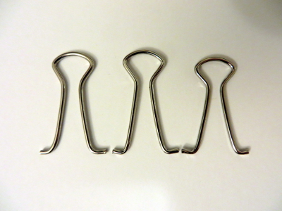
Shown above are the three characteristic families I have encountered: left to right, they are: long with a wide neck, long with a narrow neck, and short with a narrow neck. For the Impenetraball, I personally favor the smallest (i.e., short and narrow) handles, as this results in a noticeably denser grid and increased stability. However, this also makes construction significantly more difficult. More practically, I suggest just buying (or otherwise acquiring…) some clips (of the correct size!) and using whatever you end up with.

Step 2: The Basic Unit

Basic unit

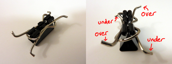
For the basic unit, take a single clip, remove the handles, and wrap them around the body as shown. Be careful to tilt the handles to match the over/under pattern labelled in the second image above, instead of its mirror image. (Note: the over/under detail is purely for aesthetic purposes and may be safely ignored for those less pedantic than I.)

Step 3: Begin Joining the Units

Joining two units

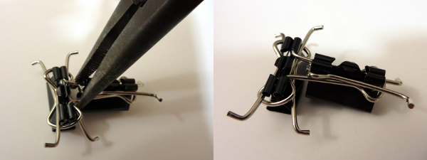
Adjacent units are joined as shown here. I strongly recommended using needle-nose pliers, especially for later steps as the ball gets tighter and more warped.

Step 4: Build a 2×3 Grid, and “In” vs “Out”

Out square (left), in square (right)

Continue building up a grid. At a 2×3 rectangle, stop to notice that one square has all of its handle curves pointing “out” toward you (shown on the left), while the other square has handle curves pointing “in” away from you (right). These “out” and “in” squares will alternate in a checkerboard pattern across the entire finished piece.

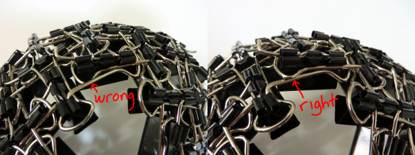
Step 5: Finish a 4×4 Face

Choosing the right 4x4

Continue building up to a 3×4 grid. We will next complete this into a 4×4 grid, but we must be careful here: there are two ways to complete the 3×4 into a 4×4, and you must choose the one that leaves an “out” square in the middle. Equivalently, the bottom-right clip in your 4×4 grid should be aligned vertically, to match the images here. Note well: this time, the careful choice is not simply one of aesthetics or pedantry. If your faces are not oriented consistently, they will not fit together later.

Finished face

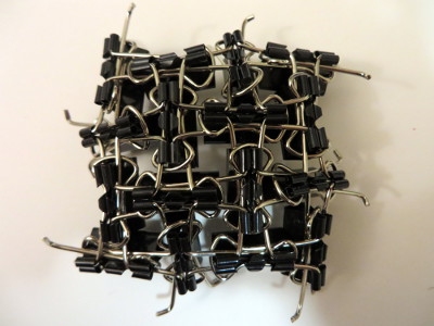
This 4×4 grid will end up being a face of a cube as explained above. You will therefore eventually need 6 of these 4×4 faces, which accounts for 96 of the 132 clips that we will use. The rest of the clips are used for the edges.

Step 6: Join two Faces at an Edge

Attaching an edge

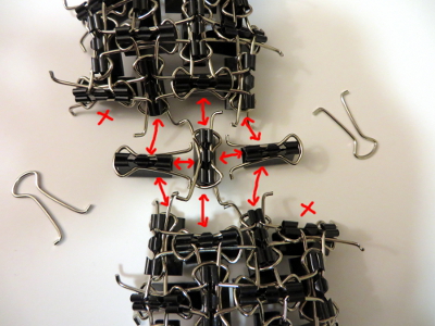
We can now begin assembling the cube by joining two faces with three additional “edge filler” clips as shown. Note that the two faces do not align straight on: the bottom face is shifted one unit to the right. (Equivalently, the two corners marked with an X are left unmatched by this edge.) This is what will leave triangular gaps at the cube’s corners. Note also that two of the “edge filler” clips are missing one of their handles. Set these aside for later use (namely, for filling corners).

Finishing an edge

To join this edge, first attach the three “edge filler” clips to one of the faces, and then join these two assemblies together as illustrated.

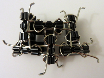
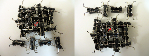
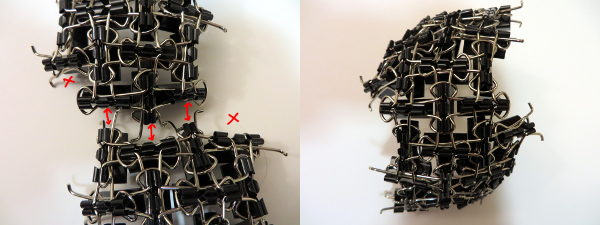
Step 7: Attach a Third Face

Attaching the third face

It is time to attach the next face just as we attached the first. There are now two cube edges being formed, so use 6 “edge filler” clips along the two edges, making sure the alignment is the same as before: at each edge, the bottom face is shifted one to the right relative to the top face. There should be a nice, symmetric triangular hole between the three faces.

Third face: progress

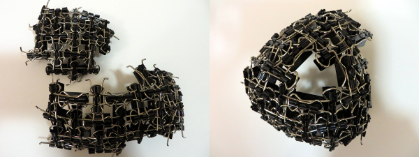
I find it easiest to attach the edge filler clips to the new face (shown left), and then joining this to the existing assembly (shown in progress on the right). Even so, this step is quite resistant. It takes a decent amount of patience and forcing, which is why pliers are essential. If you are minding the over/unders, this pattern is often disrupted by all the rough-housing (as illustrated below), so carefully check it as you go and correct it as soon as possible.

Over/under correction

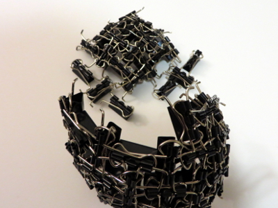
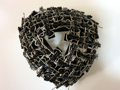
For all our troubles, here is the final three-face assembly!

Finished third face

Step 8: Close off a Corner

Filling a corner

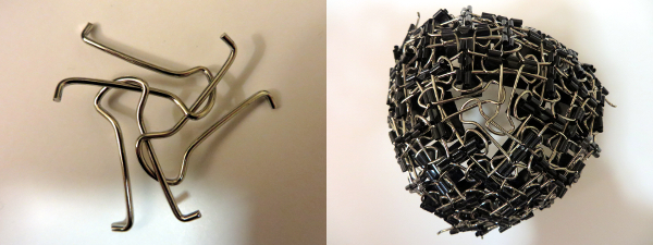
Now that one of the 8 corners of the cube is completed, we can fill it in! Take 3 of the leftover handles, weave them as shown, and insert them into the corner. You will repeat this 7 more times after the remaining corners are surrounded.

Step 9: Keep Going!

Final Impenetraball

Almost there! You now have all the tools you need to finish: there are just three more faces to join along 9 more edges, and 7 more corners to close off. All of the steps are the same as before: double-check the alignment when attaching edge filler with faces, and (I find this easier) always attach all necessary edge filler to the new face before joining to the existing assembly. If the third face was tough to attach, the rest are even more difficult, but just keep forcing things into place until it all clicks (literally). Best of luck!

Red, Alert

[This is the 4th and last installment in the current series on mini-golf and ellipse geometry. See the previous ones here: #1, #2, #3.]

We must settle one more question to round out our elliptical arc: Why does light, when shot from one focus of an ellipse-shaped mirrored room, reflect back to the other focus? To answer this question, we’ll need a Fact, a Formalism, and a Fairy Tale.

The Fact

Recall that, in the previous post, we saw that ellipses can be described by distances: Any ellipse has two focus points F1 and F2 so that the total length of broken path F1XF2 is the same for every point X on the ellipse; let d be this common total distance. In fact, more is true: the length of F1XF2 is smaller than d if X is inside the ellipse, and larger than d if X is outside.

[Ellipse Distances]
Left: The distance of the broken path is greater, equal, or less than d depending on whether the central vertex is outside, on, or inside the ellipse. Right: A proof of the “outside” case.

To prove this fairly intuitive fact, we’ll use the “straight line principle”: the shortest distance between two points is a straight line. Indeed, when X is outside the ellipse (see right diagram above), straight-line path YF2 is shorter than the path YXF2 that detours through X, and so \(\)d = F_1 Y F_2 < F_1 Y X F_2[/latex]. See if you can fill in the case where X is inside the ellipse.

The Formalism

Recall that when light bounces off a straight mirror, the angle of incidence equals the angle of reflection. But here we’re discussing light bouncing off an ellipse, which is decidedly not straight. So we need to formally describe how light reflects off curved mirrors.

[Reflection off a Curve]
Reflection off of a curved mirror behaves like reflection off of the tangent line.

If we zoom into where the incoming light ray strikes a curved mirror (illustrated above), the mirror closely resembles a straight line, specifically its tangent line. This suggests that the light should behave as if it is reflecting off of this line, with equal angles as marked. This is indeed the rule governing ideal reflections on curved mirrors: the angles of incidence and reflection, as measured from the tangent line, should be equal.

The Fairy Tale

The last ingredient involves Little Red Riding Hood and her thirsty grandmother. Red is delivering cake and wine from her mother (point M) to her grandmother (point G), but she must first fill a bucket of water at the nearby stream S, which is conveniently shaped like a straight line. She was warned by her Brothers to watch out for a big bad wolf, so she must minimize her total walking distance. Where on the stream should she fill her bucket to minimize this distance?

[Little Red's Geometry Problem]
Left: Paths from M to S to G transform into paths from M’ to G, the shortest of which is straight. Right: This straight path behaves like a mirror.

To answer this, imagine reflecting the first leg of Red’s journey across line S, so her path from M to S to G gets reflected to a path from M’ to G. The reverse may be done as well: any path from M’ to G turns into a path from M to G that stops somewhere along S. So we just need to find the shortest path from M’ to G. But this is easy: it’s just the straight path M’G. So Red’s shortest path from M to S to G is the one that stops at Z.

Notice that this shortest path is the one with equal angles as marked. This means Red’s best strategy is to pretend the stream is a mirror and to follow the light ray that bounces directly to grandma’s house. This neatly exemplifies Fermat’s principle, which says that light tends to follow the fastest routes.

The Proof

With these pieces in place, we can finish today’s question in a flash. Let’s say light from focus F1 hits an ellipse at point X, as illustrated below. Why does this ray bounce off the ellipse toward F2? If we draw the tangent line L at point X, by The Formalism above, this question is equivalent to: why does the light ray bounce off of line L toward F2?

[Reflection Off an Ellipse]
Why are the two marked angles equal? Because the white path solves Red’s Fairy Tale problem.

Let’s reimagine this Grimm scenario by thinking of F1 as Red’s mother’s house, F2 as grandma’s house, and L as the stream. I claim F1XF2 is the shortest path for Red to take. Why? If Y is any other point on line L, then Y is outside the ellipse, so by The Fact above, F1YF2 has distance longer than d. So F1XF2 is indeed the shortest. But by The Fairy Tale, we know that this shortest route behaves like light bouncing off of line L, i.e., the marked angles are indeed equal. So we’re done!

What Makes Ellipses… Ellipses?

Last time we used wild properties of ellipses to build some really easy—and some really devilish—golf courses. Specifically, I claimed that every ellipse has two magical points F1 and F2 (called foci) such that a ray from F1 always bounces off the ellipse and lands precisely at F2, and furthermore, this path always has the same length. Why does this happen? And how do we find these foci?

Let’s focus(!) on the last question first. Recall that an ellipse is a stretched circle. In other words, an ellipse is what forms when you slice a tall, circular tube (cylinder) along a slant:

Ellipses from Slicing Tubes
Left: An ellipse is formed by slicing a cylinder. Right: Fitting spheres above and below the cut locates the ellipse’s foci.

Take a sphere that snugly fits inside the tube, and drop it down until it touches the ellipse-slice at a single point F1. Do the same with a sphere underneath, touching the slice at F2. These points turn out to be the foci of the ellipse. Let’s see why.

We can use this tubular setup to answer one mystery from earlier: for any point X on the ellipse, the sum of distances of XF1 and XF2 is always the same! The proof lies in the following animation. Segments XF1 and XA have the same length because they’re both tangent to the upper sphere from X, and similarly, XF2=XB. So the sum XF1+XF2 is just the length of segment AB, the height between the spheres’ equators.

A Proof of Ellipse Path Lengths
The sum F1X+XF2 equals the length of AB and therefore does not change when X moves.

This has two neat consequences. First, it provides an elementary method for drawing ellipses (in real life!): all you need are two push pins and a loop of string, as illustrated below. The string ensures that the sum XF1+XF2 stays fixed while you trace the pen around, as long as you’re careful to keep the string taut throughout.

Drawing an Ellipse with String
How to draw an ellipse with push-pins and string

Second, what happens if we slice a cone instead of a cylinder? Perhaps surprisingly, we still get an ellipse! Indeed, as above, we can create a sphere on either side of the slice that snugly fits against the slice and the walls of the cone (the so-called Dandelin spheres), and exactly the same proof shows that XF1+XF2 stays constant as X moves around the edge.

Ellipses from Slicing Cones
Slicing a cone also produces an ellipse, by the same argument.

But wait, there’s still an unanswered question! We’ve seen that the path F1X+XF2 has a fixed length, but why does light bounce off an ellipse along such a path? This is what we really cared about for mini-golf! Come back next time for the answer, and in the meantime, have a great 2 weeks.

More Putting Predicaments

Last time we discussed some rather challenging holes of (mathematical) mini-golf, uncovering Tokarski’s construction of some un-hole-in-one-able holes. By contrast, here is the all-time easiest hole of mini-golf, namely, a guaranteed hole-in-one:

Reflections in an Ellipse
In an ellipse, any golf shot from focus \(F_1\) will bounce directly to the other focus, \(F_2\).

By some miracle of geometry, if we take an ellipse (i.e., a stretched or squashed circle) and place the ball and cup at two special points \(F_1\) and \(F_2\) called the foci of the ellipse, then any golf shot leaving \(F_1\) will bounce off a wall and proceed directly to \(F_2\).[1] You can’t miss![2]

Curiously, this easiest golf hole can be used to construct some even more challenging ones. For starters, consider a mushroom-shaped room as illustrated below (left), where the “mushroom head” is half of an ellipse with foci \(F_1\) and \(F_2\). Then the same reflection principle mentioned above tells us that any shot entering the mushroom head via segment \(F_1F_2\) will be reflected straight back through \(F_1F_2\) and sent back down the stem. This means that no shot from P can ever reach the triangular “fang” containing Q, and in particular, no hole-in-one from P to Q is possible. In the mirrored-room setting (described last time), if a light source is placed at P, then the whole triangular fang remains unilluminated! This is stronger than Tokarski’s room, where only a single point remained unlit. Similar constructions are possible even with rooms that have no corners[3], such as the “curvy” mushroom on the right.

Mushroom-shaped mini-golf holes
Left: Any path entering the mushroom head from segment \(F_1F_2\) will be reflected back down through this segment, so the triangle containing Q is not reachable from P. Right: The same phenomenon is possible even when the room has no corners.

With this idea, we can construct a mirrored room that has dark patches no matter where a light bulb is placed. In the image below, if a light source is placed anywhere in the top half of the room, the lower triangular “fang” will be completely dark. Similarly, the upper fang is not illuminated from anywhere in the bottom half of the room. This room (or one quite like it) was originally designed by Roger Penrose in 1958.

The Penrose Room
This room will have dark regions no matter where the light source is placed.

Back in the mini-golf setting, we can do something even more devious: by chaining multiple Penrose rooms together, we can construct golf holes that require as many shots as we wish! The golf hole below cannot be completed with fewer than 7 shots. Indeed, no single shot can cross two dashed segments with different numbers, so 7 shots are required.[4]

Minigolf hole needing 7 shots
At least 7 shots are required to get from P to Q.

What about polygons?

The golf holes last time were all polygons, whereas we have allowed curved boundaries here. Can we construct a polygonal golf hole, using only flat walls, that still requires at least 7 shots? Or even 3? Unfortunately, the answer this time is “we don’t know, but we think not.” In particular, it has been conjectured that, no matter where the ball and cup are placed in a polygonal golf hole, a single shot can place the ball as close to the hole as desired, so a short second putt can finish the job.[5]


Notes

  1. In fact, even more is true: all of these paths from \(F_1\) to \(F_2\) have the same length! We will not prove these facts today. []
  2. Assuming you hit hard enough, of course. []
  3. For the analysts out there, the room’s boundary can be made smooth. []
  4. This too can be accomplished with smooth boundary. []
  5. More strongly, O’Rourke and Petrovici conjecture that with a single light source in a polygonal room, the set of unilluminated points has measure 0. Reference: Joseph O’Rourke and Octavia Petrovici. Narrowing Light Rays with Mirrors. Proceedings of the 13th Canadian Conference on Computational Geometry, 137–140, 2001. []

How Unilluminating!

You are standing in a large, oddly-shaped room, all of whose walls are lined with mirrors. Everything is dark except for a single light bulb somewhere else in the room. The light from this bulb spreads out in all directions and bounces off the mirrors, possibly many times over. Is it possible that, despite all the mirrors, you could still be standing in the dark, unable to see light from this bulb from any direction?

Said differently, consider the room as a large hole of mathematical mini-golf, where the locations of the ball (just one point) and cup (also just a point) are predetermined. Your goal is to pick a direction to hit the ball, hoping that it will reflect off the walls and eventually find its way to the cup. Is a hole-in-one always possible?

Perfect Reflection
When a light ray hits a wall, it bounces off in such a way that the angle of incidence (top left) equals the angle of reflection (top right). In other words, the dashed trajectory is reflected through the line of the mirror.

We assume that when a ray of light (i.e., the golf ball) hits a mirror, it reflects perfectly, as illustrated above. Let’s also assume that it never loses energy, so it will continue as far as necessary to reach its destination. There’s one corner case to consider, namely, what happens if the ray hits a corner of the room? Well, it’s (usually) ambiguous as to where it should reflect next, so let’s say that the ray just dies if it hits a corner. In the mini-golf formulation, our hole-in-one must avoid the hole’s corners.

With these rules in place, it turns out that it is possible to be left in the dark, or to make a hole-in-one impossible! One of the first examples, provided by Tokarski in 1995[1], is illustrated below; let’s call this room R.

An unilluminable room
No light ray from P can exactly reach Q.

Let’s see why this room R works, i.e., why point Q is not illuminated by a light source at P.

Notice that R is built from identical square cells. As our ray of light continues through the room, we can keep track of where it is in its current cell—but not which cell it is in—by imagining that the ray is just bouncing around in a single square, as illustrated below. Call this single square S. We are essentially folding up the light ray’s trajectory into S.

Shooting a ray in Tokarski's room
An example light ray reflecting off the walls in Tokarski’s room, and the corresponding “folded” trajectory in a single cell (top middle). This ray gets very close to Q, but it will never reach it exactly. The grid is colored in a repeating pattern where each cell has 1 light yellow corner and three dark purple corners.

Color the grid points with light yellow and dark purple as illustrated above; in particular, P and Q are both yellow. Tokarski’s room has the interesting property that every dark purple point is in fact a corner of the room, so if the ray hits there, it dies. This means that the corresponding ray in square S would die when hitting one of the purple corners. So, in order for the light to reach Q in Tokarski’s room, the corresponding path in S must start at the yellow corner, end back at this same corner, and completely avoid the purple corners of the square. I claim this is impossible. Why?

Just as we folded room R into a single square, let’s consider unfolding square S to cover the whole plane. Because we’ve assumed perfect reflections, our trajectory in cell S unfolds to a straight line!

Unfolding the Ray
“Unfolding” the the light’s trajectory in the square produces a straight path in an infinite grid of squares.

This means that we would need to find a straight trajectory from the initial yellow point to some other yellow point that does not hit any purple points. But this is impossible: all the yellows are blocked by purples![2] So the light can’t get from P to Q in Tokarski’s room, as claimed.

This room R is not the only example of an unilluminable room; with similar methods, many such rooms may be constructed. For example, in an effort to find an unilluminable room with the smallest number of edges, Tokarski provided the 26-sided polygon below on the left, which was then improved by Castro[3] to a 24-sided polygon on the right.[4] Both are built from 45-45-90 triangles instead of square cells.

Tokarski's and Castro's "minimal" unilluminable rooms
Tokarski’s 26-sided unilluminable polygon (left) and a 24-sided modification by Castro (right).

Tokarski also provides the gem below (with no right angles!), and his paper gives recipes for a wide variety of other shapes.

Unilluminable room with no right angles
Another of Tokarski’s unilluminable rooms, this time with no right angles. The basic unit here is a triangle with angles 9, 72, and 99 degrees.

Here’s a challenge: so far, we’ve seen that it is possible to design a mathematical mini-golf hole that requires at least 2 shots. Can we make an even harder hole? Can we design one that needs at least, say, 10 shots? We’ll discuss this next time. See you then!


Notes

  1. George W. Tokarsky. Polygonal Rooms Not Illuminable from Every Point. American Mathathematical Monthly, 102:867–879, 1995. []
  2. Here’s a proof: given any yellow-yellow segment, its midpoint lies on the grid. If this midpoint is purple, then we’re done. Otherwise, take half of the original segment and repeat this argument. []
  3. D. Castro. Corrections. Quantum 7:42, 1997. []
  4. It is not known whether 24 is minimal. []

Bucky’s Dozen

Buckyballs are remarkable structures, and not just to mathematicians. In chemistry, a buckyball—more correctly, a spherical fullerene—is a molecule of carbon atoms forming a hollow spherical “shell.” Many sizes and configurations are possible (and stable!), but due to Carbon’s chemical properties they always have a few common characteristics: the faces are rings of 5 or 6 carbon atoms, and each carbon atom bonds to 3 others. The most commonly occurring one, buckminsterfullerene, is made with 60 carbon atoms in the shape of a soccer ball:

Buckminsterfullerene
The buckminsterfullerene molecule has sixty carbon atoms (green spheres) forming a “soccer ball” polyhedron.

These molecules were named after architect Richard Buckminster Fuller due to their resemblance to his famous geodesic domes. Fuller’s domes are also based on spheres built from hexagons and pentagons, and he discovered that these shapes naturally distribute forces and tensions evenly throughout the structure, thus enabling light, sturdy, and enormous constructions, such as the Climatron in St. Louis or the Montreal Biosphère.

Wait, where’s the math?

Mathematically, a fullerene is a convex polyhedron[1] where all faces are either hexagons or pentagons (these need not be regular), and 3 faces/edges meet at each vertex. The smallest of these mathematical fullerenes is the regular dodecahedron, which has no hexagons at all. The next smallest has two hexagons separated by twelve pentagons.

Smallest Fullerenes
Left: The smallest fullerene polyhedron is the dodecahedron, with 20 vertices and 12 pentagons. Right: The next smallest fullerene is the hexagonal truncated trapezohedron, having 24 vertices, 12 pentagons, and 2 hexagons.

Large and unwieldy fullerenes also exist. Some are highly symmetric with pentagons arranged at the corners of an icosahedron; others form long tubes of hexagons closed at the ends; still others display very little discernible structure whatsoever.

Larger Fullerene Examples
Left: A larger, icosahedrally-symmetric fullerene with 140 vertices and 72 faces. Middle: A tube-like fullerene with 66 vertices and 35 faces whose center is formed by a long spiral of hexagons. Right: a highly asymmetric fullerene with 44 vertices and 24 faces.

Despite their variety of appearances, they all have one thing in common:

All fullerenes have exactly 12 pentagons!

Why is this true?

One explanation comes from Euler’s beautiful formula that relates the number of vertices, edges, and faces in a polyhedron. This formula says, quite simply, that if there are v vertices, e edges, and f faces in any convex polyhedron (not necessarily a fullerene), then \(v-e+f=2\), always! For example, a cube has 8 vertices, 12 edges, and 6 faces, and indeed \(8-12+6=2\).

Let’s apply this to fullerenes. If a fullerene has \(p\) pentagons and \(h\) hexagons, then, since each edge is shared by two faces, there are \(e=\frac{5p+6h}{2}\) edges. Similarly, each vertex is shared by three faces, so there are \(v=\frac{5p+6h}{3}\) vertices. And since there are \(f=p+h\) faces, Euler’s formula tells us that

$$\frac{5p+6h}{3} – \frac{5p+6h}{2} + (p+h) = 2,$$

which indeed simplifies to \(p=12\).

So there are always 12 pentagons in a fullerene, but how many hexagons can be present? The two smallest examples tell us that 0 or 2 hexagons are possible, but 1 is not. Can we get 3 hexagons? (Yes. Try this!) What about 33 hexagons? (Harder, but yes. Try this too!) In fact, any number of hexagons is possible, with the one exception we’ve already mentioned. See if you can prove this![2] Furthermore, the number of possible fullerenes grows rapidly as the number of hexagons grows. For example, there are 1812 different fullerenes that, like the soccer ball, have exactly 20 hexagons or, equivalently, 60 vertices. With 50 hexagons (120 vertices), this number jumps to more than 52 billion different fullerenes![3]


Notes

  1. more correctly, the planar graph made by the vertices and edges of such a polyhedron []
  2. The “tube-like” fullerene from the last image provides a hint: the spiral of hexagons can have any desired length. []
  3. The exact number is 52628839448: OEIS Sequence A007894. []

Perplexing Paperclips

[I have spent the last few weeks worth of expository writing preparing the content (linked to) in this post, hence the longer-than-usual wait. Enjoy!]

Here’s a rather complicated collection of 54 loops:

Complicated collection of 54 loops

No two loops link through each other, and yet, these loops really don’t want to come apart. How hard is it to separate them? Well, suppose they were made of thin, bendable string, and we could move and (un)tangle them as much as we wanted as long as we kept the strings intact. Could we separate them? Absolutely not!

What if we allowed ourselves to cross strands through each other—real string can’t do this, of course. Then we could certainly get the loops apart, but how many such crossings would we need to use? As it turns out, we would need at least 108 strand crossings! This is a good first approximation of how much these loops don’t want to separate.

If the strands had open ends, then there would be no such knot-theoretic obstructions to building this shape. So we could, for example, make it with paperclips! (This is not easy…)

Pair o' Boxes Sculpture
The Pair o’ Boxes sculpture, made from 162 paperclips.

I call this Pair o’ Boxes, and it is one of seven new sculptures that I have recently uploaded to my Mathematical Sculpture page. More of these sculptures are shown below, and each has a detailed mathematical description (and larger pictures) at my sculpture page. Go check them out! The Pair o’ Boxes page in particular explains much more about the knot theory of the above structure, including a proof that 108 crossings are necessary to fully separate the strands.

Sculptures by Zachary Abel

Sorry for the shameless advertising; we now return to our regularly-scheduled posting.

Fibonacci-Based Arithmetic

[This is the final Wythoff’s game post. See the previous ones here: #1, #2, #3, #4, #5, #6. We’ll have a few shorter, 1- or 2-post topics starting next week.]

In our standard, base-10 number system, each position represents a specific power of 10: the number 275 in base 10 means that I have five 1s, seven 10s, and two 100s. Similarly, in the base-2 system, each position represents a different power of 2: 10011 in base 2 says I have a 1, a 2, and a 16, but no 4s or 8s.[1] Instead of using powers of 10 or 2, what happens if we use Fibonacci numbers?

We can find the Fibonacci numbers by starting[2] at \(a_1=1\) and \(a_2=2\) and then computing each term as the sum of the two previous ones, \(a_n=a_{n-1}+a_{n-2}\):

1, 2, 3, 5, 8, 13, 21, 34, 55, …

Let’s use these as our position values in our so-called Fibonacci base, using just the digits 0 and 1. For example, 1010011F stands for \(a_7+a_5+a_2+a_1 = 21+8+2+1 = 32\).

Notice that \(a_2+a_1=a_3\), so we can write 32 instead as \(a_7+a_5+a_3\), meaning 32=1010100F. In much the same way, any time we have a Fibonacci representation of a number, we can repeatedly use the identity \(a_n=a_{n-1}+a_{n-2}\) to ensure that we never use consecutive Fibonacci numbers:

Theorem (Zeckendorf): Every positive integer can be expressed in base Fibonacci with no adjacent 1s. Furthermore, this representation is unique.

The “base-Fibonacci representation” of a number usually refers to its Zeckendorf representation as in this theorem. There’s a simple greedy method to find a number’s Zeckendorf representation: use the largest Fibonacci number less than (or equal to) your number, and repeat on the remainder. For example, to represent 46 in this way, check that the largest Fibonacci number below 46 is \(a_8=34\), leaving 12 as the remainder. The largest Fibonacci number below (or equal to) 12 is \(a_5=8\), with a remainder of 4. Now we have to use \(a_3=3\), and finally we’re left with \(1=a_1\). So \(46=a_8+a_5+a_3+a_1=10010101_F\) is the Zeckendorf representation of 46.

But why discuss base Fibonacci now? What does this have to do with Wythoff’s game? Zeckendorf representations provide another simple way to characterize the losing positions in Wythoff’s game! Here’s a beautiful result:

Theorem: If \(a \le b\) are positive integers, then \((a,b)\) and \((b,a)\) are losing position in Wythoff’s game precisely when:

  • The Zeckendorf representation of a ends in an even number of 0s, and
  • The Zeckendorf representation of b is the same as that of a except for one more 0 on the end.

For example, 11=10100F ends in two 0s (two is even), and 18=101000F has the same representation except for an extra 0 at the end, so (11,18) and (18,11) are Wythoff losing positions. Unlike the formula using multiples of \(\phi\) and \(\phi^2\) that we proved in the last few posts, this provides a method we could actually compute (without a calculator) on reasonably-sized grids when playing with friends (or enemies)! After all we’ve learned about Wythoff’s game, we finally have a way to win it!

Further Reading

Our Wythoff’s game saga is now ending here on Three-Cornered Things, but here are a few recommended resources if you wish to further explore this rich topic on your own:


Notes

  1. If these concepts are unfamiliar, see this previous post on number bases. []
  2. Careful: these indices are shifted from the other common convention that starts the Fibonacci numbers at \(F_1=1\) and \(F_2=1\), which is why I’m using as instead of Fs. []

Just Beatty It

[This is the 6th post in the current series about Wythoff’s game: see posts #1, #2, #3, #4, and #5. Caveat lector: this post is a bit more difficult than usual. Let me know what you think in the comments!]

Our only remaining task from last week was to prove the mysterious Covering Theorem: we must show that there is exactly one dot in each row and column of the grid (we already covered the diagonal case). Since the rows and columns are symmetric, let’s focus on columns.

The columns really only care about the x-coordinates of the points, so let’s draw just these x-coordinates on the number-line. We’ve drawn \(\phi,2\phi,3\phi,\ldots\) with small dots and \(\phi^2,2\phi^2,3\phi^2,\ldots\) with large dots. We need to show that there’s exactly one dot between 1 and 2, precisely one dot between 2 and 3, just one between 3 and 4, and so on down the line. For terminology’s sake, break the number line into length-1 intervals [1,2], [2,3], [3,4], etc., so we must show that each interval has one and only one dot:

Multiples of phi and phi^2 on a number line
Multiples of \(\phi\) (small blue dots) and of \(\phi^2\) (large green dots) perfectly interleave the integers on the number line. This is proved below.

Why is this true? One explanation hinges on a nice geometric observation: Take any small dot s and large dot t on our number-line above, and cut segment st into two parts in the ratio \(1:\phi\) (with s on the shorter side). Then the point where we cut is always an integer! For example, the upper-left segment in the diagram below has endpoints at \(s=2\cdot\phi\) and \(t=1\cdot\phi^2\), and its cutting point is the integer 3:

Splitting blue and green dots at integers
When a segment formed by a small and a large dot is cut into a \(1:\phi\) ratio (closer to the small dot), the cutting point is always an integer. In fact, the segment between \(j\cdot \phi\) and \(k\cdot \phi^2\) is cut at the integer j+k.

In general, if s is the jth small dot—i.e., \(s=j\cdot\phi\)—and \(t=k\cdot\phi^2\) is the kth large dot, then the cutting point between s and t is \(\frac{1}{\phi}\cdot s+\frac{1}{\phi^2}\cdot t = j+k\) (Why?![1]). But more importantly, this observation shows that no interval has two or more dots: a small dot and a large dot can’t be in the same interval because they always have an integer between them![2]

So all we have to do now is prove that no interval is empty: for each integer n, some dot lies in the interval [n,n+1]. We will prove this by contradiction. What happens if no dot hits this interval? Then the sequence \(\phi,2\phi,3\phi,\ldots\) jumps over the interval, i.e., for some j, the jth dot in the sequence is less than n but the (j+1)st is greater than n+1. Likewise, the sequence \(\phi^2,2\phi^2,3\phi^2,\ldots\) jumps over the interval: its kth dot is less than n while its (k+1)st dot is greater than n+1:

Showing no interval is empty
Illustrating the hypothetical situation where interval [n, n+1] contains no dot. This is used in a proof by contradiction to show that the interval in fact cannot be empty.

By our observation above on segment \(s=j\phi\) and \(t=k\phi^2\), we find that the integer j+k is less than n, so \(j+k\le n-1\). Similarly, \(j+k+2 > n+1\), so \(j+k+2 \ge n+2\). But together these inequalities say that \(n\le j+k\le n-1\), which is clearly absurd! This is the contradiction we were hoping for, so the interval [n,n+1] is in fact not empty. This completes our proof of the Covering Theorem and the Wythoff formula!

It was a long journey, but we’ve finally seen exactly why the Wythoff losing positions are arranged as they are. Thank you for following me through this!

A Few Words on the Column Covering Theorem

Using the floor function \(\lfloor x\rfloor\) that rounds x down to the nearest integer, we can restate the Column Covering Theorem in perhaps a more natural context. The sequence of integers $$\lfloor\phi\rfloor = 1, \lfloor 2\phi\rfloor = 3, \lfloor 3\phi\rfloor = 4, \lfloor 4\phi\rfloor = 6, \ldots$$ is called the Beatty sequence for the number \(\phi\), and similarly, $$\lfloor\phi^2\rfloor = 2, \lfloor 2\phi^2\rfloor = 5, \lfloor 3\phi^2\rfloor = 7, \lfloor 4\phi^2\rfloor = 8,\ldots$$ is the Beatty sequence for \(\phi^2\). Today we proved that these two sequence are complementary, i.e., together they contain each positive integer exactly once. We seemed to use very specific properties of the numbers \(\phi\) and \(\phi^2\), but in fact, a much more general theorem is true:

Beatty’s Theorem: If \(\alpha\) and \(\beta\) are any positive irrational numbers with \(\frac{1}{\alpha}+\frac{1}{\beta}=1\), then their Beatty sequences \(\lfloor\alpha\rfloor, \lfloor 2\alpha\rfloor, \lfloor 3\alpha\rfloor,\ldots\) and \(\lfloor\beta\rfloor, \lfloor 2\beta\rfloor, \lfloor 3\beta\rfloor,\ldots\) are complementary sequences.

Furthermore, our same argument—using \(\alpha\) and \(\beta\) instead of \(\phi\) and \(\phi^2\)—can be used to prove the more general Beatty’s Theorem!


Notes

  1. Hint: use the identity \(\frac{1}{\phi}+\frac{1}{\phi^2}=1\). []
  2. To be thorough, we should also check that no interval has two small or two large dots. Why can’t this happen? []

Putting the Why in Wythoff

Last week we drew dots at multiples of the vectors \(v=(\phi,\phi^2)\) and \(w=(\phi^2,\phi)\), and we colored grid-cells green or yellow according to whether they contain a dot or not. Our remaining task was to prove these three facts:

  • Endgame condition: The cell (0,0) is green.
  • Greens lose: From a green cell, there are no other green cells accessible with a single Wythoff’s game move.
  • Yellows win: From any yellow cell, it is possible to move to a green cell with one Wythoff’s game move.
Our guess at the solution to Wythoff's game
Our guess at the solution to Wythoff's game: multiples of vectors v and w (dotted) and their containing cells (dark green).

The “Endgame” condition is easy: the dot at \(0\cdot v = (0,0)\) makes cell (0,0) green. One condition down, two to go!

The “Greens lose” condition asks us to show that no two green cells are in the same row, column, or (slope 1) diagonal—otherwise, you could get from one to the other with a Wythoff move. In fact, we will prove something stronger:

Covering Theorem: Every row, column, and diagonal contains exactly one green cell.

Pictorially, this says that each thick line in the diagrams below will hit one and only one green cell:

Covering the columns and diagonals
All columns (left), diagonals (right), and rows (not pictured) contain exactly one green cell. (Some of these green cells are beyond the image boundaries.) Because the green cell locations are symmetric through the line y=x, the diagram for the rows is redundant and therefore omitted.

It is not difficult to describe why each diagonal is covered, i.e. has exactly one green cell. In the diagram on the right, the central diagonal line has equation \(y-x=0\); the one above it has equation \(y-x=1\); the next is \(y-x=2\); and so on. And because \(\phi^2-\phi=1\), the vector v jumps from one diagonal line to the next at each step. Vector w similarly jumps from line to line in the other direction.

By contrast, I find the fact that each column is covered quite surprising. It says that the upper and lower branches of the “V” perfectly complement each other, each filling exactly the columns that the other skips! Before we prove this fact, let’s see why it helps us.

If we assume the covering theorem for now, we can finish the three conditions needed for our proof. We already saw that (0,0) is green, and the covering theorem certainly tells us that each row, column, and diagonal has at most one green cell, so the “Greens lose” condition holds. We just have to prove the “Yellows win” property: that you can always move to a green cell from any yellow cell. The idea is simple: if your yellow cell is above the “V”[1] then move down to the unique green cell in your column (which may be on either the upper or lower “V” branch). If you are below the “V”, move left to the green cell in your row. Finally, if you are inside the “V”, move diagonally. In this way, you can always move to a green cell with one Wythoff move.

Proving the "Yellows win" condition
All yellow cells can reach a green cell with one Wythoff move. Yellow cells above the "V" can move down to a green cell; yellow cells below the "V" can move left to a green cell; yellow cells inside the "V" can move diagonally to a green cell.

With this third and last property verified, we’re finally done with our proof! …except that we still need to prove the mysterious covering theorem. We’ll discuss this next week. Come back then for the exciting QED!


Notes

  1. i.e., its lower-left corner is above the line \(y=\phi\cdot x\) []