[This is post #28 in a mini-blog-post series for NaBloPoMo 2015. Jump to the first or previous post.]
The scaffold I’ve released this month is not the first I’ve designed. Thanks to feedback from a number of workshops and dedicated, private play-testers (more on these tomorrow!), I’ve been able to iteratively improve the scaffold’s design in a number of areas: ease of scaffold building, ease of scaffold use, and insight gleaned from scaffold (e.g., through symmetry, structure, variations). Today, let’s take a brief tour through some of these earlier designs.
Vertical Edges
My first scaffold was simply the first thing I thought of: vertical slices through each edge.

Straightforward in concept, but highly undesirable in most other respects. It takes forever to assemble the scaffold, with 30 individual pieces to cut and 60 flaps to tape or staple! It holds the straws quite firmly in place, with 3 holes per straw, which also helps with vertex weaving, since there’s just nowhere else the straw can go. But as a far stronger negative, this also means it has very little fault tolerance: punch a hole a few millimeters out of place, or tape not quite perfectly, and the straws just won’t go.

This scaffold hardly assists with assembly. It’s not clear what markings would help direct straw insertion and weaving, nor is it easy to print accurately on both sides of the paper anyway, so at this workshop I asked the students to rely on counting instead of reference marks—an extraneous and unenlightening mental burden.
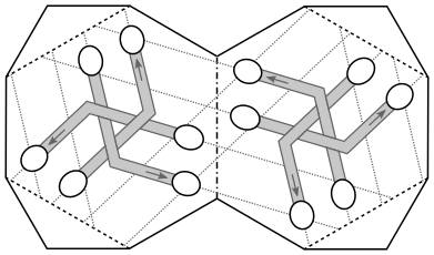
On the positive side, this scaffold demonstrates a pleasing symmetry: you can make the mirror image with the exact same scaffold!
There’s a similar version for the lacier Straws Thingy variant as well.

Horizontal Edges and Snakes
My next family of scaffolds focus on horizontal bands across the edges. This first try also has 30 separate pieces (one per edge) that are nearly rectangular, which reduces cutting complexity significantly, but it still takes a while to join all the pieces.

Joining multiple edges into larger assemblies drastically and pleasingly reduces assembly time without affecting cutting time much—a clear win.

This horizontal paradigm also lets us play with helpful reference marks. Some to point straws in the right direction, others to indicate straw color or grouping. I toyed with cute little ghosties to indicate color groupings, possibly with ghost shading or ghost mouths (look closely—that’s A through E!) corresponding to color groupings.

But I still disliked this general paradigm, for a few reasons. For one, relentlessly stabbing smiling, innocent ghosties through their eye sockets felt like cute aggression taken one step too far. But mostly, this scaffold leaves vertex weaving wide open and unaided, and this is the part people struggle with the most! Unlike the previous (vertical) scaffold, this one holds the straws fairly loosely, so it won’t mind if you accidentally spiral your vertex the wrong way… until you do it 5 or 6 times. Then it minds quite a bit. And this crying infant of a scaffold isn’t expressive enough to tell you why it’s upset, or to tell you much about vertex weaving at all! For this reason it felt immature, incomplete, to the point where I even considered a separate “vertex insert” to help with the weaving step.
Vertex-centric Scaffold
This most recent vertex-first scaffold perspective nicely solves this concern.

I’d like to say I jumped here straight from the “vertex insert” idea, but the truth is more interesting: while making the set of 32 nearly identical Straws Thingys[], a friend[] suggested I design a reusable scaffold, instead of demolishing and restarting each time. I ultimately came up with this design, where each hexagon lifts straight over its vertex without ripping.

But even if the reusable scaffold idea doesn’t survive past these 32[], the resulting vertex-first paradigm shift has been quite valuable!
Improvements?
Future improvements will be driven by your feedback! I would love to hear about your Straws Thingy experience, so don’t hesitate to let me know how it goes.
Notes